
Most pilots are roughly familiar with the power setting principals of piston engines, and even of the power setting principals of piston engines driving constant speed propellers. But for turbine engines, power is expressed in terms of “N1” and “N2.”
Because turbofan engines generate thrust rather than power (as it is traditionally expressed), turbofan engine power settings are expressed relative to rotation speed limits. These terms express power in a fundamentally different way and require understanding the mechanical concepts behind turbine engines.
So, what do N1 and N2 for turbine engines mean?
N1 and N2 express the rotational speed of turbine engines as a percentage of the maximum normal operating RPM. N1 is the speed of the low pressure spool and serves as the primary power setting, and N2 is the speed of the high pressure spool which indicates if aircraft systems have sufficient power.
In order to better understand N1 and N2, we need to start with the basics of turbine engines. Later in the article we’ll cover practical applications of N1 and N2 readings. Let’s jump in!
How Do Turbine Engines Operate?
Typical turbofan or turbojet engines are comprised of 5 major sections: the inlet, compressor/fan, combustor, turbine and nozzle.
Air is drawn through the inlet, pulled through the fan and compressor to increase its pressure, mixed with fuel and burned in the combustor, exhausted through the turbine and accelerated through the nozzle to produce thrust.
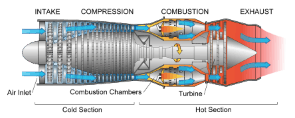
For this discussion, the compressor and turbine are the components of interest.
The compressor section is generally comprised of two sections, the fan and low pressure compressor and the high pressure compressor. Similarly, the turbine is comprised of a high and low pressure section, the high and low pressure compressors are linked to their respective turbine counterparts via concentric and independent drive shafts. This means that the low pressure and high pressure sections rotate independently of one another.
The mechanical principal behind turbine engines is fundamentally that the turbine section(s) are able to extract sufficient energy from the exhaust to drive the compressor section(s), which provide sufficient air to burn to feed the turbine.
This means lighter, more thermodynamically efficient turbines and compressors become more efficient.
Depending on the engine, the high and low pressure compressors and turbines may be a single stage or multiple stages. There are handfuls of large turbofan models that operate with three spools instead of the typical two, though this discussion will be limited to two spool designs.
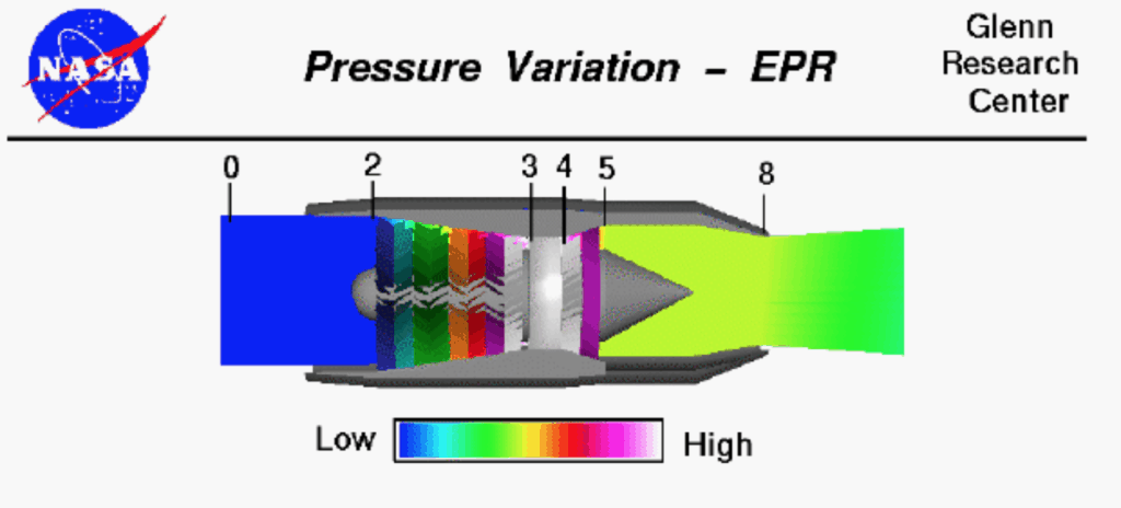
Image Source
For more information on the operational concepts of turbine engines, refer to the three-part engine comparison series here:
Piston vs. Turboprop: Safety, Efficiency, and Performance
Turbojet vs. Turbofan: Safety Efficiency and Performance
Turbofan vs. Turboprop: Safety Efficiency and Performance
What Defines N1 and N2?
N1 is the rotational speed of the low pressure turbine and compressor spool expressed as a percentage of the maximum normal operating RPM of the spool.
N2 is the rotational speed of the high pressure turbine and compressor spool expressed as a percentage of the maximum normal operating RPM of the spool.
These speeds will differ from one another as each spool rotates independently from the other. It is common that at a steady state operating condition N1 and N2 will differ substantially, particularly at lower power settings. This is important, as each spool needs to operate independently to ensure proper pressure gradients through the engine.
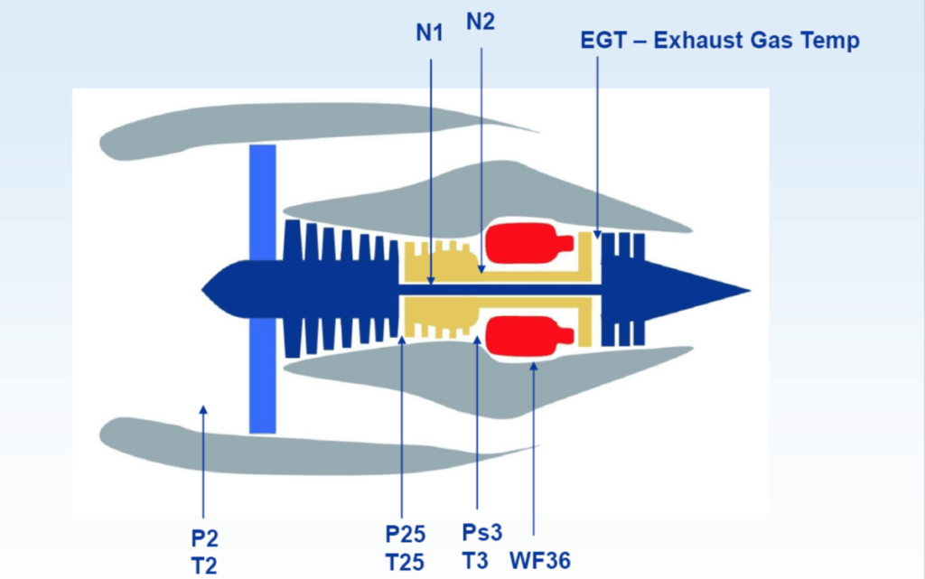
Image Source
How Do Pilots Use N1 and N2 to Set Power?
The use of N1 and N2 are dependent on the phase of flight and the operating requirements of various systems that use the engine for power.
In order to illustrate this concept, the Pratt and Whitney PW306C/D family of engines as installed in a Citation will be used as a reference. Different engines may require or specify different operating procedures, but the concepts are reasonably conveyed by the PW306C/D.
N1 is the primary power setting speed during takeoff, cruise, and approach to landing. N2 serves as the primary reference for determining sufficient power delivery to aircraft systems, including bleed air systems, generators, hydraulic pumps, fuel pumps or other engine driven accessories.
To illustrate the practical implementation of these speeds, consider a generic engine flight profile.
Engine Start
The electric starter is engaged to drive the high pressure spool to generate airflow through the engine. Fuel may be introduced by activating the FADEC upon reaching a minimum rotation speed of 9% N2. A stable, successful start and idle is partially indicated by an N1 value of 57% (other system indications corroborate a successful start). During the start sequence, normal start progression is verified by N1 rotation and acceleration as well as starter disengagement at 40% N2.
Systems Tests
Bleed air systems required for flight such as pressurization and anti-ice systems are checked by reference to N2 speeds and the Inter-Turbine Temperature (ITT). A minimum N2 of 75% is required to generate sufficient bleed air pressure and flow to heat the anti-ice system to pass the pre-flight check. Pressurization checks verify ITT changes according to bleed switch selection and minimal change in N2 speed, N1 speed by contrast varies slightly as bleed air valves are closed and opened.
Takeoff, Climb, Cruise and Approach
After advancing the throttle to the takeoff position, the pilot verifies the N1 FADEC speed bug and N1 speed indication match. The pilot will continue to verify N1 speed indications match the FADEC target throughout the flight. The N2 speed is monitored to verify normal engine operation, but is largely non-critical to crew duties, excepting the need to conduct an inflight restart. During the approach phase of flight, an approximate N1 speed of 60% to 65% is used to maintain the approach speed while flying a 3° approach path.
Shutdown
The crew conducts the normal engine shutdown procedures, delaying shutting down the batteries and avionics until after N2 speeds have dropped to 0% to ensure safe spool down of the engine and that fuel has been cutoff appropriately by the FADECs.
Why is N1 Used to Set Power?
The N1 value of an engine is indicative of the health of the engine’s intake and compressor section. The pressure gradients that ensure good operating characteristics are determined by smoothing of the pressure gradient by the engine’s fan and low pressure compressor.
N1 is indicative of how much energy is entering the nozzle to become thrust because it is reflective of the speed of the final, low pressure turbine.
In contrast N2 fluctuates substantially less, even with substantial power reductions. Two factors affect this: rotating mass and energy extraction by the high pressure turbine.
Relatively speaking, the high pressure turbine has less total mass to accelerate and it has the highest total exhaust energy available to accelerate that mass, so even at idle power settings, N2 remains relatively “spooled up.” This mechanical reality makes N2 a difficult to use value for setting power.
Why is N2 Used to Manage Systems?
For the PW306C/D bleed air is extracted at the high pressure turbine and the accessory drive is linked to the high pressure spool. Therefore N2 becomes the value that determines if engine driven systems are receiving sufficient power to operate normally.
Hydraulic pumps, fuel pumps, generators and alternators all require sufficient rotational speed to operate normally. Similarly the amount of bleed air available from the engine is a function of the speed of the compressor section.
N2 also indicates the health of the combustion cycle, because the high pressure spool is the first to react to changes in the combustor via the high pressure turbine, N2 is an excellent indicator of normal operating health.
How Do Turboprop Engine Speeds Differ From Turbofan/Turbojet Engine Speeds?
For the purpose of this discussion, the Pratt and Whitney PT6A will be considered, primarily because of its ubiquity in the turboprop market. The basic concepts discussed apply equally to most turboprops.
Because turboprops are generating thrust via their propeller, the N1 and N2 speeds no longer directly apply.
Instead, propeller RPM and torque are used to set power while N1 is used to monitor system health and control engine starts (note N1 and NG are generally interchangeable values for turboprop engines).
Critically, the N1 speed is not linked to the high or low pressure spool, because the turbine and the compressor operate on independent shafts.
The N1 speed is measured at the combustor output to the power turbine. In the PT6A this speed controls a pressure relief valve that helps to maintain the appropriate pressure gradient inside the engine. It also indicates whether the engine is accelerating properly during engine start.
Torque is measured on the output shaft of the turbine section, and in the case of the PT6A it is function of oil pressure. Propeller RPM is the output speed of the reduction gearbox, also powered by the turbine shaft.
For turboprop engines, torque becomes the primary power setting value as engine output is most directly limited by either torque or ITT.
Conclusion
Turbofan and turbojet engines are rated for normal operation according to their rotational speeds. As a result engine performance is monitored according to the rotation speeds of the low pressure and high pressure spools. Turbofans use the N1 speed, which measures low pressure spool speed to set power and the N2, which measures high pressure spool speed to manage accessory system performance.


