

The Turn and Slip Indicator and Turn Coordinator are very similar. In fact, the Turn and Slip Indicator and Turn Coordinator show some of the same data. But, there are important differences as well.
What is the difference between the Turn and Slip Indicator and the Turn Coordinator?
The difference between the Turn and Slip Indicator and Turn Coordinator is that the Turn and Slip Indicator shows the rate of heading change, and the Turn Coordinator indicates both the rate of heading change as well as the rate of roll, or movement of the aircraft around the longitudinal axis.
Let’s explore how the Turn and Slip Indicator and the Turn Coordinator are the same, how they are different, and how to fly with each.
First, how do gyroscopic instruments work?
To compare the difference between these two instruments, it’s really important for a quick refresher on how gyroscopic instruments work in the first place.
Gyroscopic instruments, like the Turn and Slip Indicator and the Turn Coordinator, rely on a spinning gyroscope housed within the instrument.
The gyroscope, spinning at 10,000-15,000 revolutions per minute, exhibits rigidity in space. This means that the gyroscope itself will remain in one place as the aircraft moves around it – subject to the limitations of the gimbals it is mounted upon.
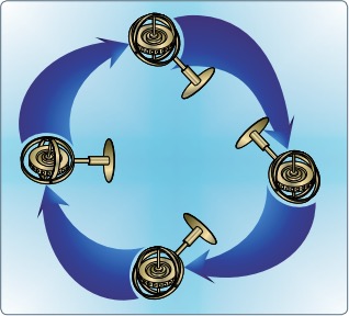
Image Credit: Chapter 8 of the Pilot’s Handbook of Aeronautical Knowledge
The second force that applies to gyroscopes that is important to understand is gyroscopic precession.
Gyroscopic precession is the movement of a gyroscope in response to forces acting upon it.
As illustrated below, if force is applied to a spinning gyroscope, there will be a resultant force 90 degrees in the direction of rotation.
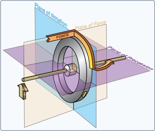
Image Credit: Chapter 8 of the Pilot’s Handbook of Aeronautical Knowledge
The turn and slip indicator’s gyroscope is mounted in such a way so as to negate any effect of gyroscopic precession. However, the turn and bank indicator uses gyroscopic precession to present rate of bank information.
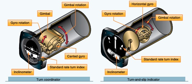
The Turn and Slip Indicator
The more basic of the two instruments, the Turn and Slip Indicator, is actually two instruments in one.
Most of the face of the instrument is taken up by a turn needle, attached to the gyroscope inside the case of the instrument, and three indices.
The index at the top of the instrument is where the needle will point when there is no rate of turn being detected. The index at either side of that, usually with an “L” on the left and an “R” on the right.
The L and R indices are oftentimes each referred to as a “doghouse” due to their shape.
In most general aviation aircraft, when the turn needle is aligned with either doghouse, that indicates a standard rate turn of 3 degrees per second. In higher-speed aircraft, there could also be indicators for half-standard rate turns.
At the bottom of the turn and slip indicator is the “ball” or the inclinometer. Both the turn and slip indicator as well as the turn coordinator utilize the inclinometer. There will be more on this in a moment.
Why does the rate of turn matter?
The rate of turn for a given bank angle (assuming coordinated flight – more on that in a moment) decreases as speed increases.
Within the ATC environment, air traffic controllers are expecting slower moving aircraft to change heading at the standard rate of three degrees per second.
At a typical Cessna 172 speed of 100 knots true airspeed, this equates to about 15 degrees of bank (using the 10% of true airspeed +5 rule of thumb… the actual formula is a bit more complicated).
Now, let us climb into our Boeing 737 that is cruising at a true airspeed somewhere in the neighborhood of 500 knots.
Applying that rule of thumb gives us a bank angle at cruise of approximately 55 degrees to achieve 3 degrees per second!
Well, since the airlines enjoy having customers, the airlines and ATC settle for a more reasonable 1.5 degrees per second rate of turn expectation resulting in a 22.5 degree bank angle.
Turn and Slip Indicator Limitations
The good news is that the Turn and Slip Indicator is mounted in such a way that the gyroscope will not tumble.
This means that, even in unusual attitudes, the Turn and Slip Indicator is measuring the rate of heading change accurately. The bad news is that it is not a reliable instrument for indicating the actual bank angle or roll rate of the aircraft.
This is an important factor to consider when flying on instruments in a partial-panel situation when you do not have an attitude indicator.
The important thing to remember is that while it will not indicate the rate of roll, the Turn and Slip Indicator can be used to level the wings of the aircraft without the use of an attitude indicator but only in coordinated flight.
This shortcoming of the Turn and Slip Indicator led to the discovery that gyroscopic precession could actually make the instrument a bit more useful.
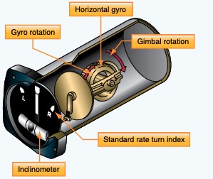
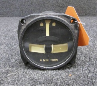
The Turn Coordinator
The Turn Coordinator is very similar to the Turn and Slip Indicator with one important exception; the gyroscope within the instrument is not mounted along the longitudinal axis as it is in the Turn and Slip Indicator, but at a 30-45 degree angle with the front of the gyroscope being higher than the rear.
Earlier in this article we recalled how annoying gyroscopic precession is as it relates to having to reset the heading indicator so often. Well, gyroscopic precession is not all bad.
By mounting the gyroscope at an angle, gyroscopic precession can now be used to displace the instrument indicator (the aircraft silhouette) in a way that indicates the rate of roll.
Then, once the aircraft heading begins to change, the instrument indicates the rate of turn in the same way that the Turn and Slip Indicator does.
So now, rather than just indicating movement about the vertical axis like the Turn and Slip Indicator does, we get an indication within the cockpit of movement about the vertical and longitudinal axis with the Turn Coordinator.
During VFR flight, the instrument is useful because it can be more easily used to coordinate our turns during the banking process.
As the aircraft banks, it may take a moment for a rate of turn to develop. With a Turn Coordinator, the instrument can be referenced while banking to measure both the rate of bank and, by monitoring the inclinometer, learn how much rudder is needed to combat adverse yaw and keep everything coordinated.
There is, however, no substitute for learning the correct feeling in the seat of your pants and keeping your head up and out of the cockpit during VFR flight.
Turn Coordinators in Glass Avionics
Those of us flying behind digital panels have turn and slip/skid indicators as well.
The difference is that they are combined with other instruments and rather than relying on a spinning gyroscope, the AHRS (attitude and heading reference system) generates the outputs that get translated into the instrument readings.
The turn indicator is typically along the top of the HSI and is really a heading trend indicator along with up to two indices, one for half-standard rate and one for standard rate heading changes.
The slip and skid indicator is located just under the roll pointer. It is a small horizontal line that moves to either side indicating a slip or skid just as a ball would within an inclinometer.
Just like the ball, the pilot “steps on the line” by applying rudder to whatever side the line is until it is centered beneath the roll pointer.
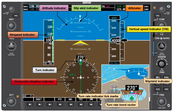
Image Credit: Chapter 8 of the Pilot’s Handbook of Aeronautical Knowledge
Practical Considerations for Using Turn and Slip Indicators and Turn Coordinators
The Inclinometer: An Included Feature of Both Instruments
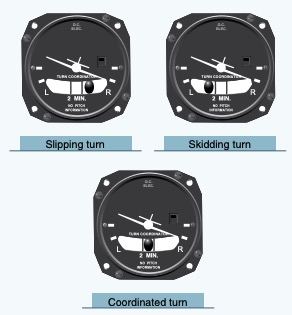
The other indication on the face of both the Turn and Slip Indicator and the Turn Coordinator is the inclinometer.
This liquid filled tube has a slight curve to it and contains a ball. The ball will indicate how coordinated – or not – you are without regard to the bank angle.
At some point or another, our instructor said to us, “step on the ball!” This is the ball to which she was referring.
By keeping the ball between the two lines, we can be assured that gravity or centrifugal force, if in a turn, is acting straight “down” on the aircraft along the vertical axis.
If the aircraft is slipping, the ball will fall towards the inside of the turn meaning more rudder is required in the direction of the turn.
If the aircraft is skidding, then less rudder is needed in the direction of the turn input is the way to go.
Either way, if the pilot “steps on the ball” and applies the correct amount of rudder to whatever side the ball is on, coordinated flight will follow.
For more reading on this topic, see our article on slipping vs. skidding turns and the danger associated with them.
Turn and Slip Indicator vs. Turn Coordinator in IFR
It is during IFR flight, though, that the real value of this important difference between the two instruments comes into play especially during partial-panel flight by reference to the instruments.
A quick glance at the Turn Coordinator will tell the pilot if the aircraft is moving about the longitudinal axis, i.e. rolling. This is why, during partial panel operations, the Turn Coordinator becomes the primary bank instrument.
The other reason why the Turn Coordinator is a primary bank instrument when partial panel is because of its power source.
Unlike most traditional attitude indicators, the Turn Coordinator in most modern aircraft is electrically powered. This provides redundancy in case of a vacuum failure.
Preflight Checks
The Turn and Slip Indicator and the Turn Coordinator are checked in similar ways during the preflight inspection and before takeoff.
Upon first entering the cockpit during preflight, the inclinometer should be observed. It is important to ensure that the glass tube is completely filled with liquid and that there are no bubbles visible.
Also, take a look at where the ball is sitting within the glass tube. If it is resting outside the lines on the glass tube but the aircraft appears to be sitting level along the longitudinal axis with neither wingtip above the other, this might be worth exploring a bit more.
Gently shake the aircraft by the wingtip and see if the ball moves to a more appropriate resting place.
After startup and as you are taxiing out to the active runway, take a look at the instrument while executing a turn. The turn needle or aircraft silhouette should indicate a turn in the direction you are turning and the ball should indicate a skidding turn by moving to the outside of the turn.
Additionally, the instrument, if electrically powered, should not be indicating any red flags. If vacuum powered, then the suction gauge is checked as is typical during the runup checklist.


