
Conducting flight operations according to Instrument Flight Rules (IFR) adds significant flexibility and capability for aircraft that meet the equipment requirements of IFR flight. Aircraft produced and registered according to a “standard airworthiness certificate” are demonstrated as capable of IFR flight by the manufacturer. But can you fly IFR in an experimental aircraft?
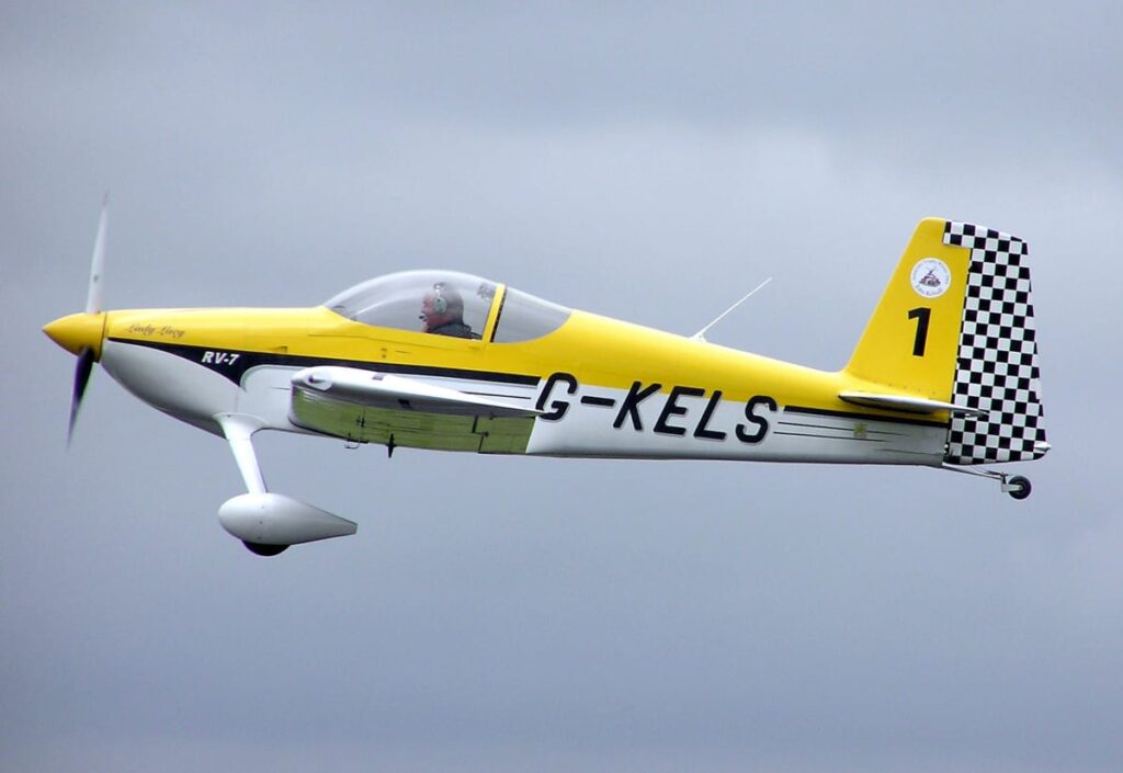
Flight under IFR rules in experimental aircraft is permitted so long as the aircraft limitations and the installed equipment meets the requirements for IFR flight under 14 CFR 91.205. Some experimental aircraft have flight characteristics less optimal for IFR flight, however with the required equipment, IFR flight is entirely acceptable.
Flight under IFR rules is governed by two primary sets of requirements, the aircraft operating limitations and the required equipment specified by 14 CFR 91.205. For experimental aircraft, the builder or owner has wide latitude in selecting the installed avionics equipment. If IFR flight is a desired capability for the aircraft, the builder or owner must install equipment sufficient to meet the navigational requirements of IFR flight and the requirements of 91.205.
Additionally, builder or owner must state as part of the airworthiness limitations that the aircraft has been flight tested and is permitted to conduct IFR operations according to the equipment requirements of 91.205.
Let’s cover the required equipment for all types of flight (VFR day and night, as well as IFR) and then also cover some practical implications of flying IFR that go beyond just the regulations.
What are the Equipment Requirements of 91.205 for VFR Flight?
For aircraft operating in the United States, 14 CFR 91.205 specifies the aircraft equipment required to be installed for VFR, IFR, Day and Night operations. Day VFR equipment is the minimum required to have an airworthy aircraft and is detailed in 91.205 (b) as follows:
- Airspeed indicator.
- Altimeter.
- Magnetic direction indicator.
- Tachometer for each engine.
- Oil pressure gauge for each engine using pressure system.
- Temperature gauge for each liquid-cooled engine.
- Oil temperature gauge for each air-cooled engine.
- Manifold pressure gauge for each altitude engine.
- Fuel gauge indicating the quantity of fuel in each tank.
- Landing gear position indicator, if the aircraft has a retractable landing gear.
- For small civil airplanes certificated after March 11, 1996, in accordance with part 23 of this chapter, an approved aviation red or aviation white anti-collision light system. In the event of failure of any light of the anti-collision light system, operation of the aircraft may continue to a location where repairs or replacement can be made.
- If the aircraft is operated for hire over water and beyond power-off gliding distance from shore, approved flotation gear readily available to each occupant and, unless the aircraft is operating under part 121 of this subchapter, at least one pyrotechnic signaling device. As used in this section, “shore” means that area of the land adjacent to the water which is above the high water mark and excludes land areas which are intermittently under water.
- An approved safety belt with an approved metal-to-metal latching device, or other approved restraint system for each occupant 2 years of age or older.
- For small civil airplanes manufactured after July 18, 1978, an approved shoulder harness or restraint system for each front seat. For small civil airplanes manufactured after December 12, 1986, an approved shoulder harness or restraint system for all seats. Shoulder harnesses installed at flight crew stations must permit the flight crew member, when seated and with the safety belt and shoulder harness fastened, to perform all functions necessary for flight operations. For purposes of this paragraph—
- The date of manufacture of an airplane is the date the inspection acceptance records reflect that the airplane is complete and meets the FAA-approved type design data; and
- A front seat is a seat located at a flight crew member station or any seat located alongside such a seat.
- An emergency locator transmitter, if required by §91.207.
- [Reserved]
- For rotorcraft manufactured after September 16, 1992, a shoulder harness for each seat that meets the requirements of §27.2 or §29.2 of this chapter in effect on September 16, 1991.
Tip: Need a handy way of memorizing this list or others? Here is one of our favorite videos from the Airplane Academy YouTube channel that provides a SUPER easy way to memorize various acronyms and lists in aviation (and any other topic, really). We hope it helps!
Also, be sure to subscribe to our channel so that you never miss a video!
Setting aside 91.205(b) (11) – 91.205(b) (17), it is apparent that the basic day VFR equipment requirements are minimal relative to IFR equipment. The FAA is primarily concerned with ensuring the pilot of a Day VFR aircraft is able to monitor his or her airspeed, altitude, heading, fuel state, and engine health. Day VFR rules and equipment requirements are built around the concept of looking outside the window to navigate and avoid terrain.
Night VFR equipment as described by 91.205(c):
- Instruments and equipment specified in paragraph (b) of this section.
- Approved position lights.
- An approved aviation red or aviation white anti-collision light system on all U.S.-registered civil aircraft. Anti-collision light systems initially installed after August 11, 1971, on aircraft for which a type certificate was issued or applied for before August 11, 1971, must at least meet the anti-collision light standards of part 23, 25, 27, or 29 of this chapter, as applicable, that were in effect on August 10, 1971, except that the color may be either aviation red or aviation white. In the event of failure of any light of the anti-collision light system, operations with the aircraft may be continued to a stop where repairs or replacement can be made.
- If the aircraft is operated for hire, one electric landing light.
- An adequate source of electrical energy for all installed electrical and radio equipment.
- One spare set of fuses, or three spare fuses of each kind required, that are accessible to the pilot in flight.
Slightly more equipment is required, primarily associated with lighting and electricity generation. These regulations ensure that other aircraft will be capable of seeing the aircraft at night and that there is a means of powering these lights that exists independent of a battery system. Navigation is still intended to be a visual exercise, even on the darkest of nights (though there are notable safety implications associated with attempting such a feat).
What are the equipment requirements of IFR flight?
The FAA specifies in 14 CFR 91.205(d) the instrument flight rules equipment requirements. These addition equipment requirements markedly increase the instrumentation burden and systems requirements for aircraft operating under IFR rules.
- Instruments and equipment specified in paragraph (b) of this section, and, for night flight, instruments and equipment specified in paragraph (c) of this section.
- Two-way radio communication and navigation equipment suitable for the route to be flown.
- Gyroscopic rate-of-turn indicator, except on the following aircraft:
- Airplanes with a third attitude instrument system usable through flight attitudes of 360 degrees of pitch and roll and installed in accordance with the instrument requirements prescribed in §121.305(j) of this chapter; and
- Rotorcraft with a third attitude instrument system usable through flight attitudes of ±80 degrees of pitch and ±120 degrees of roll and installed in accordance with §29.1303(g) of this chapter.
- Slip-skid indicator.
- Sensitive altimeter adjustable for barometric pressure.
- A clock displaying hours, minutes, and seconds with a sweep-second pointer or digital presentation.
- Generator or alternator of adequate capacity.
- Gyroscopic pitch and bank indicator (artificial horizon).
- Gyroscopic direction indicator (directional gyro or equivalent).
These regulations are squarely aimed at ensuring the pilot can maintain his attitude, and follow a safe course without reference to the outside world. These equipment requirements increase the need for reliable vacuum and electrical power resulting in aircraft systems that must be dependable and ideally, redundant in the event of a failure.
What Operating Limitations Are Required?
As part of the experimental / homebuilding process, the aircraft must undergo flight tests to ensure it is safe and does not have any unusual hazards associated with its construction or design. At the outset of this process an Operating Limitations entry is recorded specifying what equipment is installed according to 91.205, and that until the flight testing phase is complete, the aircraft is restricted to Day VFR conditions.
Once this testing phase is complete, the aircraft is then permitted to conduct night and IFR operations. The builder is required to specify what operations are approved for their aircraft. This means that the flight testing period is critical for determining that the installed equipment works properly and that there are no issues that would preclude safe flight, particularly IFR flight.
These operating limitations are not notably different than those encountered by pilots of aircraft assigned a standard airworthiness certificate. The operating limitation must specify what equipment must be installed to conduct flight under day / night and VFR / IFR rules, what maneuvers are approved, and under what circumstances these various operations may occur.
Ultimately the local FAA office must concur with the limitations proposed by the builder, ensuring that the aircraft will meet the requirements of both homebuilding and equipment regulations.
Practical Considerations for IFR Flight in Experimental Aircraft
Equipping a homebuilt aircraft for IFR flight is reasonably straight forward. There are requirements for navigation equipment to meet IFR standards, particularly for GPS navigation sources, and fortunately cost effective and highly capable options are widely available to homebuilders.
Selecting the equipment to be reliable, redundant in the event of failures, and appropriate to the aircraft itself is a more difficult challenge. Redundant systems for airspeed, altitude, attitude, and navigation should be a priority for experimental aircraft intended to be operated in IFR conditions.
Backup Airspeed and Altitude
Whether installing a “glass” panel or round dial panel (see: Glass Cockpit vs. Steam Gauges: 7 Factors Compared), a redundant display of critical flight parameters should be strongly considered, while this need not include for example redundant pitot-static systems, a second altimeter and airspeed indicator are useful backups. Particularly for “glass” panels, where altimetry data is dependent not on a mechanical gauge but on a single set of pressure transducers, back up airspeed and altitude data displays should be a priority.
Backup Attitude
Similar consideration should be given to attitude information. The gyroscopic instruments that provide attitude and heading data may be powered electrically or by vacuum. Either power source should be considered prone to failure. Vacuum pumps will fail as readily as alternators or generators. Therefore when selecting power sources three avenues are typically available: dual vacuum systems, vacuum / electric combinations, and an all electric system.
Dual vacuum systems are the least common installation as few aircraft engines support a dual vacuum pump installation (light twins are the most common users of a dual vacuum system). The most common implementation of instrument power redundancy is the vacuum / electric combination.
In this arrangement gyroscopic instruments are duplicated entirely across both types of power source. The new generation of electronic standby flight displays are excellent candidates for this type of arrangement, particularly in aircraft with older instrumentation installations.
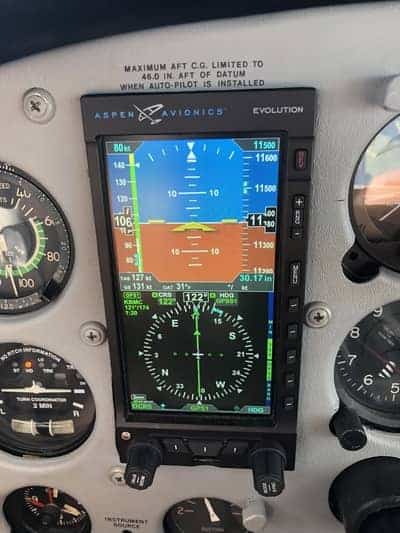
Finally, the all electric installation relies on dual alternator or generator installations or on standby batteries to provide backup power to electrically driven gyros. This type of installation is becoming increasingly popular as electronic flight instruments shrink in both size and cost.
Backup Navigation
Navigation sources are easily duplicated with modern avionics equipment, the proliferation of inexpensive communication and navigation radios and IFR GPS equipment allows a builder or owner a range of options for redundant navigation capability.
Typically a dual radio configuration and at least one GPS allows for robust communications and backs up the ground based navigation sources with GPS; though the proliferation of GPS approaches suggests that practically speaking the navigation radios back up the GPS receiver in most aircraft using the IFR system.
Builders and owners of experimental aircraft have broad leeway to equip their aircraft for IFR flight but simply meeting the minimum requirements of 14 CFR 91.205 should be carefully considered. An aircraft intended to be used in the IFR system on a regular basis should incorporate redundant systems that make the aircraft’s avionics tolerant of equipment failures.
Experimental Aircraft Design Considerations for IFR Flight
The broad range of experimental aircraft kits and plans available is impressive. Many of these designs are on par with the certified offerings of the major general aviation manufacturers. For the homebuilder or future owner looking for an IFR capable experimental aircraft, some care should be taken prior to selecting a design.
IFR flight demands a stable, predictable and easy to fly aircraft that alleviates pilot workload where possible.
While aerobatic aircraft may be excellent for competition or joy riding on nice evenings, these types of aircraft may be challenging in IFR conditions due to reduced longitudinal stability and light control forces.
Similarly, aircraft designed for maximum speed may make ergonomic compromises that make sustained IFR flight uncomfortable or difficult for the pilot. The FAA in their certification rules specify minimum standards for a wide range of aircraft design criteria, but for IFR flight the notable concerns are stability requirements, control force requirements and communication and navigation requirements.
Most, if not all, homebuilt aircraft fall under the Part 23 certification regulations, and while experimental aircraft offer the distinct benefit for not need to comply with these requirements they offer a good guide for the types of design considerations that should be made for an experimental aircraft intended to be used as an IFR platform.
Stability requirements are laid out in the 14 CFR 23.145 – 23.181 regulations (for the purposes of this discussion the amendment 63 and earlier rules will be referenced). These rules set minimum requirements for longitudinal, lateral and directional stability as well as overall control forces.
Needless to say, a long dissertation could be written on the interactions of these rules, and those dissertations have been written, including by the FAA (See AC 23-8C).
The certification stability requirements emphasize that the aircraft should be easily controllable, should have control forces that are appropriately high as to make over control issues non-existent, but yet allow the pilot to maneuver easily and that the aircraft shouldn’t make the pilot work too hard to maintain safe flight while maneuvering.
For an experimental aircraft intended for IFR flight, these rules should be a framework for considering the suitability of a design for conducting IFR operations. Extremely light control forces, weak stability (particularly in pitch and roll), poor trim characteristics etc. all make IFR flight a more difficult challenge, and thus reduce safety margins while attempting to safely fly without outside visual references.
The 1300 series of the Part 23 rules deal with installed equipment and the proper operation of that equipment in a wide range of operating conditions. Again, dissertations on these regulations may be written and continue to be written.
The essence of the systems and equipment regulations are that if a piece of equipment is installed in the aircraft it should work and should not interfere with the flight crew’s ability to operate the aircraft safely.
So, for all of the autopilots, radios, displays, antennas and instruments installed in the aircraft, each component should perform their specified and desired function, work in harmony with each other, and not interfere with each other’s function.
Additional guidance is found under the TSO process which ensures a piece of equipment meets requirements for its design, construction and operating conditions. While TSO equipment is not required for experimental aircraft it does provide a level of assurance that the equipment is suitable for the desired operation.
Conclusion
IFR flight in experimental aircraft is acceptable, provided the aircraft has passed its flight test period, meets the equipment requirements of 14 CFR 91.205 and has the appropriate statements in the operating limitations.
Beyond these basic requirements attention should be paid to ensuring that the aircraft design and equipment is suitable for IFR flight. The equipment should offer redundancy and protection against system or instrumentation failures. This redundancy ensures that the pilot can continue to safely operate in poor weather at least temporarily.
The aircraft’s equipment and equipment should also be reliable and perform the functions it was installed to perform in conjunction with the other aircraft systems and equipment.
The design of the aircraft should provide a stable, predictable and easy to fly platform for instrument flight. While this does not require an experimental aircraft to meet FAA certification rules, those rules do provide a good guide against which to measure a given experimental design.
The Experimental Aircraft Association (EAA) discusses this topic and a vast array of other experimental aircraft considerations on their website, which is an invaluable resource for experimental aircraft builders and owners (EAA and IFR Flying).


